|
|
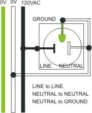
OD-1 Why we need better outlet testers. by John Roberts 2016 DC voltage like in our car battery, has a + and – polarity so current only flows in one direction. AC voltage like in our outlets, alternates back and forth, so has no positive or negative direction. The electrical energy supplied to our outlets in the US is typically 120V AC “alternating current” electricity. Because of this when reading an AC voltage with a Volt-Ohmmeter (VOM) you can reverse the meter leads, and still get the exact same reading. The widely available 3-lamp outlet testers, because of this characteristic of AC current flow can only detect when an AC potential exist between two outlet leads, not which lead is hot and which is grounded. This lack of polarity information prevents detecting reversed wiring errors. An outlet with line and neutral reversed and open ground does not report properly with the 3 lamp tester. (UL makes them add fine print to the instructions that the 3 lamp tester can not detect multiple errors). Since Line and Neutral are both insulated inside appliances this reversal is generally harmless, but not always (see Wiring Error #2 below). Wiring Problem) #1 missing ground
open safety ground Some older residences were built using only two circuit wiring (like my house). When adding modern grounded outlets to older 2-wire buildings, if you do not have a safety ground available,you can install a Ground Fault Circuit Interrupter (GFCI) protected outlet that protects humans even without a ground connection. The GFCI will cut the power if it senses more than 5 mA of current leaking from an appliance plugged into that outlet.
Bootleg Ground DO NOT bootleg or jumper safety ground to neutral. In theory they are both 0V, so a bootleg jumper connection “could” provide a safety ground bond current return path, adequate to trip a branch circuit fuse or breaker in case of a line to chassis (safety ground) short circuit. But DO NOT DO IT. Bootleg grounds are dangerous because any break in the neutral wire going back to the electrical panel would cause neutral current from any equipment plugged into the outlet to flow into the safety ground while seeking a return path. During such an “open-neutral” fault the equipment chassis grounds can be dangerously energized to a major fraction of the line voltage potential. Wiring Error (problem) #2 “Reverse Polarity”.
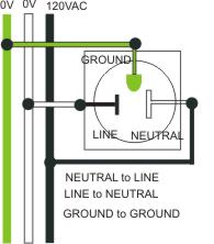
reverse polarity A common wiring error (a few outlets in my house are reverse polarity) is to swap the wiring between line and neutral. Since appliances operate from the AC potential between line and neutral, they generally will not notice the reversal. I do not want to make a big deal about this because it is not much of a safety problem. It can cause some noise problems with audio gear that expect neutral to be a quiet 0V instead of noisy 120V. Line and neutral are both insulated from chassis ground inside appliances, and 2 wire plug appliances have an additional layer of insulation inside (per UL). Wiring Error (BIG problem) #3 “Reverse Polarity Bootleg Ground”
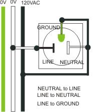
reverse polarity bootleg ground The already illegal practice of bootleg grounds, becomes deadly hazardous in combination with a swapped line-neutral feed (see schematic image above). Now instead of the bootleg ground connecting to the 0V neutral, it connects safety ground to 120V. This wiring mistake can and does kill*** people. Problem #4. Test equipment that measures wiring errors like RPBG and reports it as OK.
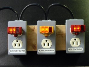
In this picture (supplied by Mike Sokol), we see examples of three wiring scenarios, being measured by the widely used commercial 3-lamp outlet tester. The first properly wired 3 circuit outlet indicates correct wiring. The second 2 circuit outlet with a “bootleg ground to neutral” connection also indicates as good because neutral and ground are both nominally 0V. The third outlet reveals an almost unbelievable problem. The RPBG wiring is literally connecting 120V to the safety ground, dangerously energizing the chassis of any appliance plugged into such an outlet. This widely used commercial outlet tester does not detect or indicate any problem at all! This is due to the previously mentioned lack of single direction for AC current flow. This dangerous outlet tester can not tell the difference between a Line properly energized, with neutral-ground at 0V, or the complete opposite, line at 0V and ground-neutral energized at 120V. (Danger Will Robinson). UL recognizes this flaw but only makes the manufacturer of such flawed outlet testers add some fine print to their instruction sheet, warning that the 3-lamp tester can not detect multiple faults. The UL approved 3-lamp tester will not shock you by itself, but using it to test your outlet wiring can be hazardous to your health. Be sure to have your lawyer read that fine print warning…. if you survive a RPBG incident.
|
The solution…. The OD-1 (outlet detective) outlet tester uses a novel technology that delivers reliable detection of dangerous outlet mis-wiring.
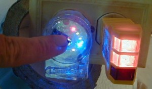
OD-1 reveals RPBG In this image, the OD-1 on the left and common 3-lamp tester on the right are both plugged into an outlet with Reverse polarity bootleg ground. When I touch the momentary test button, while plugged into a RPBG outlet, the red “Ground is hot” LED correctly indicates that the safety ground is energized and causing a dangerous safety hazard. The yellow “Neutral is hot” LED also lights up. The commercial three lamp tester falsely reports PRBG as “all safe”, while the OD-1 correctly reveals the danger present from a hot safety ground and also detects the swapped line/neutral that the commercial tester completely missed when in combination with bootleg ground. Note: The OD-1 touch probe exceeds the > 100M @ 500V insulation resistance requirement that UL considers fully insulated for any exposed metal, by a factor of 5x. So the OD-1 touch contact is completely safe.
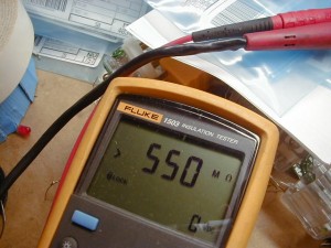
550M @ 500V Since the OD-1 is not commercially available another useful piece of test gear is the NCVT “non-contact voltage tester”. This device can identify an energized safety ground without even having to touch it. Some cheap ones are too sensitive to easily parse out outlet wiring, but can definitely identify an energized appliance chassis and hazards like that. Be safe and stay alive.
*** While I was working at Peavey, years ago, we got sued when a musician was electrocuted between two UL approved Peavey guitar amps. One of the two amps was plugged into a RPBG mis-wired outlet, energizing the strings to 120V. The other guitar was properly grounded. When the musician held the guitars plugged into the two amps, one in each hand, the mains current flowed through his body and killed him. The judge exonerated Peavey and condemned the house until the hazardous wiring was repaired. -------------------------------------------------------------------------------- The better way, a test circuit that catches RPBG
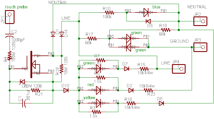
OD-1 outlet tester full schematic (no secrets or omission) This outlet tester combines a high impedance buffer that generates a true environmental 0V reference when touched by a bare finger, with current steering diodes to illuminate different color LEDs to register energized outlet contacts. If the safety ground is energized the red LED lights up while the probe is touched to report this hazardous wiring fault. If the line and neutral are reversed, energizing the neutral (not hazardous by itself but wrong) the yellow LED lights up to warn about the wiring fault. Finally if the line is properly energized the green LED lights to report proper wiring. Another green LED reports presence of a ground path (it does not test the quality of that ground path). How it works The blue LED at the top of the schematic serves as an always-on power present or outlet energized indication whenever there is AC voltage between line and neutral (this does not test for polarity just AC voltage present.) Next, green LEDs sense for presence of a ground path and illuminate when either line or neutral is energized and a ground path is present. Next three strings of colored LEDs connect to the low impedance source (buffered output) lead of the high input impedance MOSFET, that provides a relatively low impedance (nominal) 0V node. Steering diodes selectively direct current through the LED paths during the negative half cycle of mains voltage for LED strings connected to energized outlet leads. For most cases only one LED is energized, but for RPBG both the ground and neutral LED illuminate. Revealing the presence of both wiring errors and the hazardous energized ground. The input buffer circuit is less obvious and the result of many hours of bench work, including multiple generations of prototypes. The paramount design goal for a metallic contact touched by humans is safety. This circuit was designed to meet UL standard S-1436_5, the standard covering the cheap 3-lamp testers. Since S-1436 does not anticipate a touch contact, I decided to design it to pass the insulation resistance criteria 100M @ 500V (DC). This was not trivial since small SMD resistors tend to misbehave at very high voltages, but slightly larger more expensive resistors can handle the voltage. Then I added an input capacitor making the measured (DC) input impedance even higher. I can't confirm the actual input impedance since it reads off-scale above the range of my (borrowed) test equipment >550M @ 500V. While not immediately obvious (it took me a while to figure this out) but the touch probe is not establishing a local 0V DC reference, but a local capacitor coupled AC 0V reference. While perhaps difficult to visualize the buffer MOSFET receives mains voltage from either line or neutral. A large value resistance in parallel with the MOSFET trickles a small current to the source node. With the input probe floating this MOSFET is cut off so source and gate swing slightly positive, clamped near 0V mains voltage by the forward biased ground and/or neutral LED strings. During the negative half cycle the floating gate-source swings almost to the negative mains voltage. However when the gate is touched by a human, the capacitance to AC 0V is enough to cause the MOSFET to turn on during the negative half cycles and illuminate the appropriate indication LEDs. There are no unneeded parts in this design. Every part serves some useful function. In my judgment this circuit PCB mounted inside an already UL approved plug should pass UL testing to meet or exceed S-1436. It surely exceeds the UL mandated caveat warning that these other 3-lamp testers can't detect multiple wiring flaws, because this one does. I opened discussions with UL, but at this point I am unwilling to invest the $10,000+ to just open a file. My unconventional "touch probe" reference approach would likely involve even more discussion and approval costs. The OD-1 is not available for purchase at this time. I would love to partner with a manufacturer already making similar products to help bring this to market. Since I have openly shared this design this technology is free to use. I will add a more specific BOM and a workable PCB layout, while any serious manufacturer need to tool up their own version.
Partlist Exported from out_test_1d.sch at 9/22/2016 12:15:19p EAGLE Version 4.03 Copyright (c) 1988-2001 CadSoft Part Value Device Package Library C1 .001uf C-USC0805 C0805 rcl C2 1000pF C-USC0805 C0805 rcl D1 DSOD-123 SOD-123 SMT D2 DSOD-123 SOD-123 SMT D5 DSOD-123 SOD-123 SMT D6 ZNR-S-MINI S-MINI SMT D7 DSOD-123 SOD-123 SMT D8 DSOD-123 SOD-123 SMT D10 DSOD-123 SOD-123 SMT D14 DSOD-123 SOD-123 SMT JP1 PINHD-1X1 1X01 pinhead JP2 PINHD-1X1 1X01 pinhead JP3 PINHD-1X1 1X01 pinhead JP4 PINHD-1X1 1X01 pinhead R1 100M 1206 R-US_R1206 R1206 rcl R3 1.5k R-US_R0805 R0805 rcl R6 1.5k R-US_R0805 R0805 rcl R7 1.5k R-US_R0805 R0805 rcl R10 100k R-US_R1206 R1206 rcl R15 15k1/4w R-US_R1206 R1206 rcl R16 15k1/4w R-US_R1206 R1206 rcl R17 68k R-US_R1206 R1206 rcl R18 68k R-US_R1206 R1206 rcl R20 10M 1206 R-US_R1206 R1206 rcl R21 75M 1206 R-US_R1206 R1206 rcl R23 15k1/4w R-US_R1206 R1206 rcl U$1 BSS8787 SOT89 JOHN U$2 LEDL 0805LED JOHN U$5 LEDL 0805LED JOHN U$6 LEDL 0805LED JOHN U$9 LEDL 0805LED JOHN U$12 LEDL 0805LED JOHN U$13 LEDL 0805LED JOHN
c.2016 |

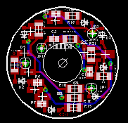 PCB that fits inside
Leviton 8215-CAT-15A plug
PCB that fits inside
Leviton 8215-CAT-15A plug